FAQ

To be able to help you quickly and easily, we have compiled the frequently asked questions and their answers here. You will certainly find the information you are looking for here or on the rest of our website. If not, please do not hesitate to contact us via our contact form.

Contact us

The basic SFERAX ball bearing is composed of :
– A housing made of ball bearing steel, machined, hardened to 65 HRC +0 -3, ground and lapped except the B quality, which is only precision-ground
– Brass turned and milled ball tray (GBL) or in polyamid for the GBP execution
– Precision steel balls
– Steel locking rings and plastic control rings injected after assembling

Approx. 0,002. Reduced friction allows heavy loads to be shifted longitudinally with a minimum expenditure of power, hence energy.

Depending on the application and the dimension, from 0,002 to 0,02 mm on the shaft diameter.

For Standard SFERAX 5 m/sec. In case of ball-bearing movement, the speed at the end of the stroke must be decreased.

Standard SFERAX 100 m/sec2
Special SFERAX 150 m/sec2

For rapid acceleration/deceleration, we recommend using Bearings reinforced by dowel pins. Ball bearings with an inner diameter of 100 mm or more are fitted with dowel pins as standard.

For Standard SFERAX - 30° + 80°C
For Special SFERAX, type BL- 30° + 140°C.
For SFERAX type HT, SMX, COMPACT and HL - 30° +200° C.

– Thin bodied oil - for high speeds
– Dry if necessary
Max. speed 1 to 2 m/min (without seal)
– Lithium-based grease. For instance, for horizontal applications and medium speeds. Choice of viscosity depends on speed; the higher the speed is, the lower the viscosity should be.

Rectified benzine, petroleum, compressed air.

SFERAX ball bearings are delivered with a anti-corrosion product. This product is not a lubricant. It is recommended to remove it and lubricate the bearing properly.

When fitting SFERAX ball bearings, extreme care should be taken (just as for radial bearings).
For best results and to ensure precise fitting, the bearing should be pressed into the housing using a mandrel 0,1 mm smaller than the housing bore. It should be square to the bearing and in contact with the outer housing only (see illustration 1). The ball bearing can be held in place by being slightly tightened without hold or left to slide freely and fastened by screw nut, circlips, end cover, etc. It can also be bonded (see product sheet).

 Fig. 1 Illus. 1


Where two ball bearings are to be used in tandem, it is recommended that the shaft be inserted into the ball bearings prior to bonding in place.

More than 60 years of experience in the manufacture and application of SFERAX ball bearings testifies to our claim that linear ball bearings in general, and SFERAX in particular, have contributed directly to the improved performance and longer life of all types of high technology machines, with reduced energy consumption.
Below are some guidelines for the installation and calculation of the service life of SFERAX bearings. Any mechanical ball bearing construction requires compliance with certain rules. Failure to observe these basic precautions will in one way or another impair faultless operation. Nevertheless, we would remind users that ball bearings are fragile elements requiring due care. The following rules should always apply:

– A high degree of cleanliness
– Avoidance of shock loads
– Correct alignment of the ball bearing and shaft
– Adequate lubrication
– Correct loading of the ball bearing and shaft.
– Appropriate temperature
– Careful adjustment (bearing and shaft)

The shaft deflection should always be calculated, as this may dictate that a larger diameter bearing is required (see frequently asked questions). It is easily understandable that a shaft bent under the load is not supported by all the balls of the bearing. Normally a deflection larger than 0,01 mm with respect to the length of the supporting balls is unacceptable, unless the ball bearing is strongly over dimensioned for the actual load.

Note: the fact that a bearing is preloaded is a factor in reducing its service life. 

Sferax S.A. is not liable if the above-mentioned conditions are not fully met.
 

We use the same formula for calculating the working life expectation of ball bearings of all qualities.
Ball bearings with a higher level of precision have a much longer working life than those with wider tolerances, although the latter support more play.

The tables describing the dimensions and the characteristics of the ball bearings also include a factor Y, determined by the allowed static load.
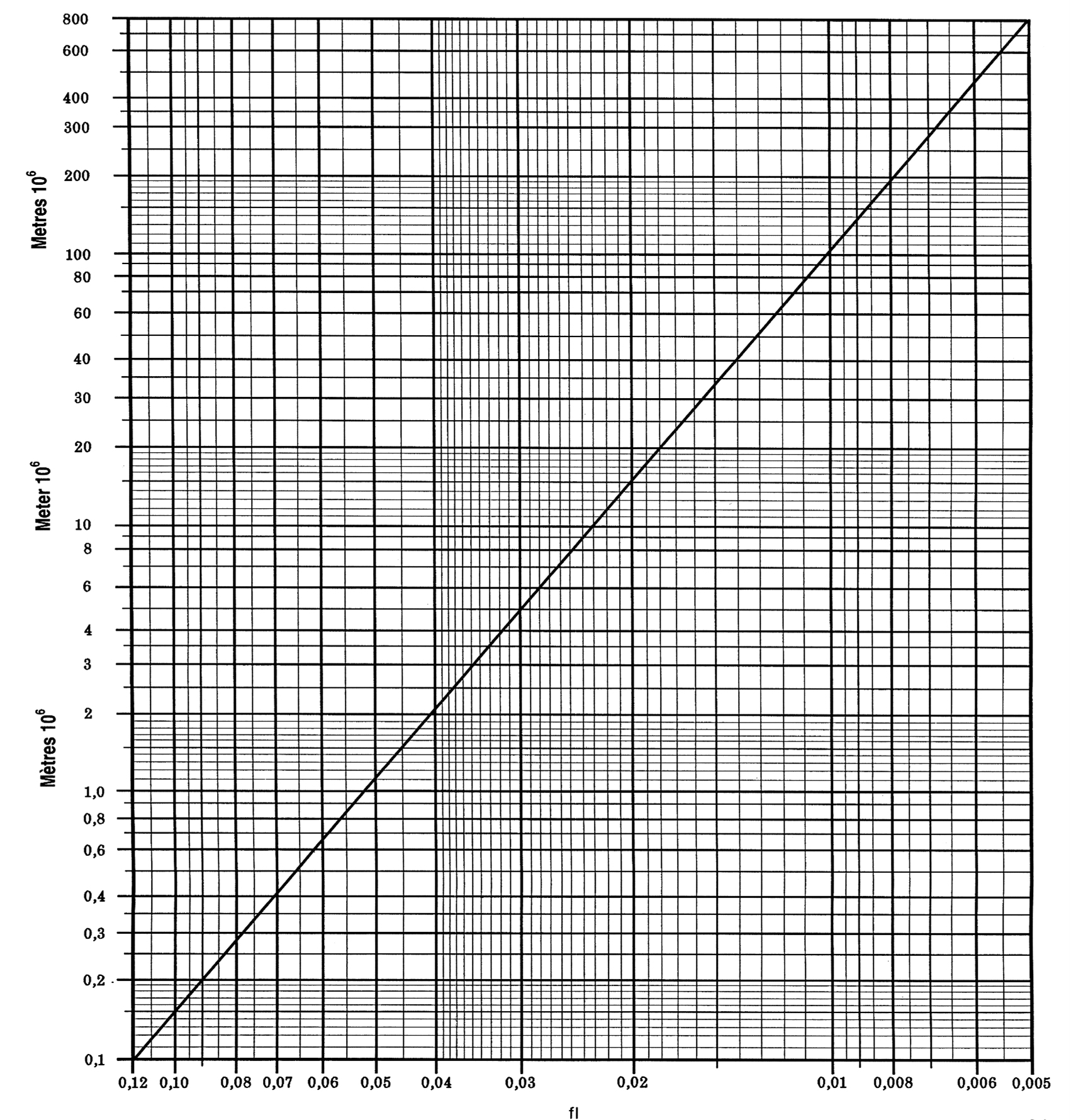
These first measurements allow you to obtain the fl factor according to the formula:
fl = X • Y • P
fl = coefficient of the working life expectation 
X = coefficient of shaft hardness
Y = dynamic coefficient of the ball bearing
P = load perpendicular to the ball bearing [Kp]
The Diagram 1
gives us the working life expectation in metres.

The working temperature influences the working life expectation and must be taken into consideration in the calculation by the Z factor according to Table 2.
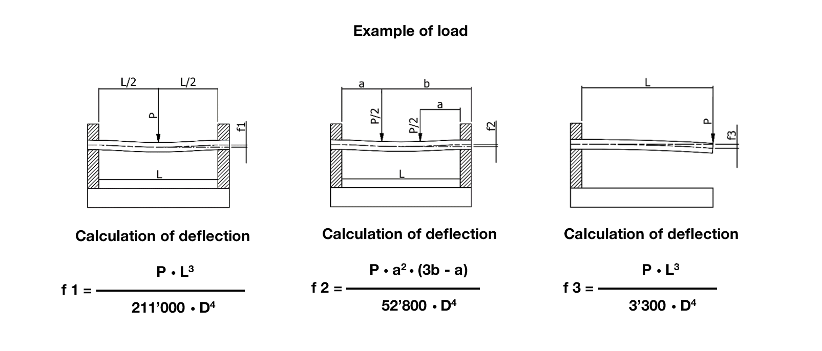
The given formula is valid for a maximum deflection of 0,001 mm along the total length of the supporting balls. It is imperative not to use untempered hard-chrome shafts. In case of doubt, do not hesitate to consult us before starting a new combination. We are at your disposal for all information, and will not hesitate to advise against the use of a SFERAX ball bearings when the
application is unsuitable.
 

Example

These calculations are only theoretical and therefore do not necessarily correspond to the actual conditions. SFERAX SA cannot be held responsible for them.

The vertical charge of the machine slide is 100 kp*), moving on 2 shafts and supported by 4 type OUV ball bearings. Each ball bearing carries 25 kp*). The stroke slide is 400 mm, moving 200 times per minute.
Shaft hardness: 60 HRC.
Working temperature: 120° C.
Preferred shaft diameter: 30 mm
 

P = 25 Kp*)
Y = 0,000152 (see product sheet)
X = 1,1 (Table 1)
Distance run per hour = 0,4 • 2 • 60 • 200 = 9’600 m/h.
fl = X • Y • P = 1,1 • 0,000152 • 25 = 0,00418
Working life at 120° C = plus de 800’000’000 (diagram 1)
Working life at 120° C. = 0,92 • 800 • 106 = 736 • 106 m (Z = 0,92)
Working life in hours = (736 / 9'600) • 106 = 76’666 hours.

*1 Kp = 9.81 N


Table 1
Coefficient of the Shaft Hardness


Rockwell C


X


Rockwell C


X


Rockwell C


X

51

1,93

56

1,27

61

1,085

52

1,74

57

1,19

62

1,07

53

1,58

58

1,15

63

1,06

54

1,45

59

1,12

64

1,05

55

1,35

60

1,10

65

1,04

Table 2
Temperature Coefficient

Temp.
° Celsius


Z

80°

1,00

125°

0,92

140°

0,88

150°

0,85

180°

0,77


Diagramme 1

Fig. 2

To guarantee continuously smooth operation, shaft deflection should be minimal. A maximum deflection of 0,01 mm between the first and last outer balls in the ball bearing is acceptable.
f 1 = deflection under central load in mm.
P = load in kp. 
L = distance between the supports in mm.
D = diameter of the shaft in mm.
f 2 = deflection for a load shared on two symmetrical points with respect to the center, in mm.
a = according to drawing.
b = according to drawing.
(modulus of elasticity for steel 22’000)
f 3 = deflection under a load acting on the free end, in mm.


Fig. 3